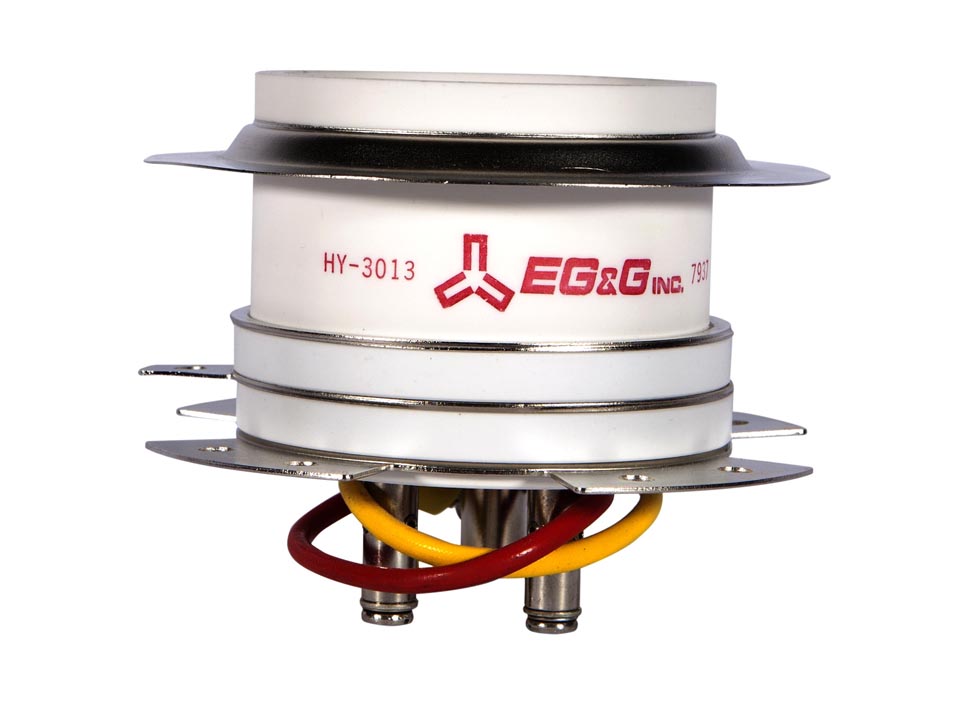
HY-3013 Low Inductance Tetrode Thyratron 25 kV 1.5 kA
We no longer offer this product. If you want repair service or a custom modern equivalent, contact us.
Includes
- New HY-3013 low-inductance thyratron
EG&G's hydrogen and deuterium-filled thyratrons are high voltage, high current switch tubes that utilize ceramic-metal construction for small size and extended life. Operation at peak anode voltages as high as 125 kV is possible with some types; peak anode current ratings range from 100 A to 40 kA. Applications include radar modulators, accelerators, and pulsed gas lasers.
-
Peak Forward Anode Voltage When Tube is Operated in Oil or Insulating Gas to Prevent External Breakdown (Between Flanges) in Air. For operation in air, epy must be appropriately reduced.
-
Peak Forward Anode Voltage (Resonant or Command Pulse Charging on Millisecond Time Scales). Higher epy is generally attainable with command charging on microsecond time scales; resistive charging significantly degrades the attainable epy.
-
Peak Forward Anode Current (5-Microsecond Pulse). For sub-microsecond pulse widths at pulse repetition rates below 1000 Hz, several times the rated ib can usually be reliably attained. For long pulses, ib must be substantially reduced.
-
Average Anode Current. For rectangular current pulses at a fixed pulse repetition rate, Ib equals the product of ib, the pulse width, and the pulse repetition rate, prr.
-
RMS Anode Current. For rectangular current pulses at a fixed pulse repetition rate, Ip = SQRT(iblb)
-
Plate Breakdown Factor (Indicator of Anode Dissipation for Low Rates of Anode Current Rise). Pb = epy x ib x prr.
-
Peak Forward Grid Voltage (Measured at Socket with Tube Removed).
-
Effective Output Impedance of Grid Driver (Includes any Protective "De-Spikers"). In general, the lowest Zg in conjunction with high egy will provide the shortest anode delay and the minimum delay time jitter.
Click Here to Download More Info
Specifications
Peak Forward Anode Voltage |
25 kV |
|---|---|
DC Average Current |
2 A |
RMS Anode Current |
47 A |
Plate Breakdown Factor |
50x109 |
Cathode Heater Power |
6.3 V @ 11-18 A |
Reservoir Heater Power |
6.3 V @ 3-6 A |
Number of Stages |
1 |
Control Grid Open Circuit Peak Trigger Voltage (Min.) |
450 V |
Control Grid Trigger Source Impedance (Max.) |
400 Ω |
CONTACT
JOIN US
ABOUT US