40200 Rail-Gap Switch 120 kV 750 kA
We no longer offer this product. If you want repair service or a custom modern equivalent, contact us.
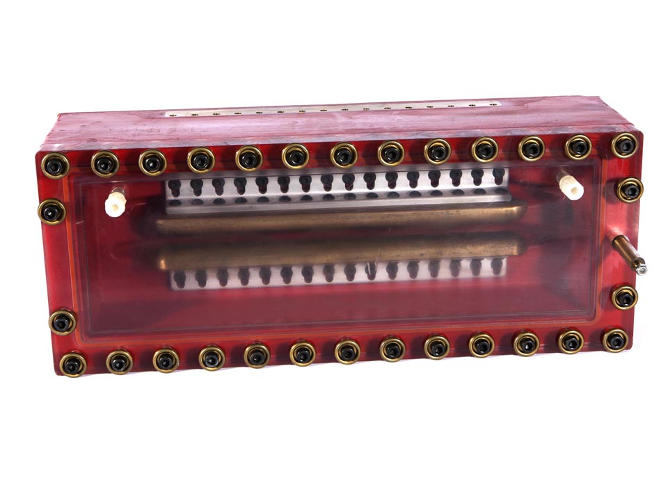
This is a an L-3 Pulse Sciences (formerly Maxwell Laboratories) 40200 rail gap switch. This switch appears to have been fired very few times as the brass rails show no sign of pitting. Also included is a copy of the user's manual with full descriptions of installation and operation.
The Model 40200 rail-gap switch is a gas-plasma switch with long, parallel electrodes (the rails for which the switch is named). The electrode rails act as multiple spark channels to provide a switching capacity comparable to multiple single-channel switches connected in parallel.
Rail-gap switches are used in applications requiring low inductance, fast rise time, and high current and high charge-transfer capability. They are often used in flat-plate transmission line assemblies, configured in either the bipolar or single-polar mode. They can also be adapted to assemblies with coaxial cable transmission lines.
Rail-gap switches can be connected in parallel and function as either start or crowbar switches, with up to four switches per application. They are most often operated at voltages in the 50 to 100 kV range, but may be set to function in the following voltage ranges:
• 25 to 50 kV
• 30 to 60 kV
• 50 to 100 kV
• 60 to 120 kV.
The rail-gap switch operates at a maximum voltage of 120 kV, peak current of 750 kA, and charge transfer capability of 10 C. Switch inductance is 20 nH. Time-delay jitter (one standard deviation) is less than 2 ns.
The switch consists of three parallel 12-inch electrodes mounted on an epoxy base with a transparent polycarbonate cover. During operation, the switch interior is filled with a pressurized mixture of argon and SF6. Connections for the gas lines are on the top side of the cover.
The trigger electrode is a knife-edged rail positioned between two brass main electrodes mounted on electrode holders. Slotted holes in the holders allow adjustment of the gap between the main and trigger electrodes. Gap adjustments can modify the operating voltage range of the switch. The terminal for the trigger electrode is on top of the switch cover. Brass contact strips on the sides of the switch base serve as terminals for the two main electrodes.
Specifications
Maximum Voltage |
120 kV |
|---|---|
Active Switching Length |
12 in |
Maximum Conducted Charge per shot |
10 C |
Dielectric Environment |
Synthetic Air, SF6, or oil |
Dielectric Gas for Lowest Jitter |
15% SF6, 85% argon by volume |
Inductance |
0.02 μH |
Minimum Voltage |
25 kV |
Output Jitter |
2 ns |
Maximum Peak Current Output |
750 kA |
Maximum Trigger Amplitude |
100 kV |
Minimum Trigger Risetime |
5 kV/ns |
Rated Life |
5000 |
CONTACT
JOIN US
ABOUT US