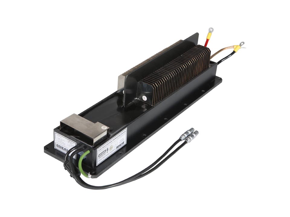
Behlke Fast High Voltage Transistor Switch 30 kV 30 A Push-Pull

We no longer offer this product. If you want repair service or a custom modern equivalent, contact us.
Includes
- 1) Behlke HTS 301-03-GSM high voltage transistor switch
- 2) Panel-mount LEMO sockets that mate with control cables
Tested by Hofstra Group
- Installed in test circuit recommended by Behlke
- Verified performance at maximum voltage and rep rate in air without forced cooling
- Inspected with infrared imager while operating at maximum rep rate and voltage
- Performed extended hi-pot test at max rated voltage in air to verify integrity of insulation
The switching modules of the series HTS-GSM consist of two identical MOSFET switching paths that form a so-called half bridge circuit respectively push-pull circuit. Both switching paths are controlled by a common driver, which also provides a logic signal negation for one of the switches. The switches are mutually passively locked, so that a short in the bridge is excluded under all circumstances, including if the control input is disturbed by electromagnetic interferences (due to bad EMC design, for example). Especially in pulse generator applications with capaci- tive load, the push-pull principle has considerable advantages in comparision with the conventional circuitry using a single-switch with a working resistor. Push-pull circuits do not require large energy storage capacitors for a low pulse drop and, because there are no working resistor power losses, the efficiency of a push-pull pulser is excellent regardless of pulse width, frequency and duty cycle. The pulsers draw only currents for charging the connected load capacitance. Thanks to an extremely precise timing of the switches, there are also almost no cross currents in the bridge, except peak charging currents of the switch natural capacitances.
The switches are controlled by positive going signals of 3 to 10 V amplitude. Fault conditions as over-frequency, thermal overload (long-term overload) and incorrect auxiliary supply set the switching path A in off-state and the switching path B in on- state. Faults are indicated as a low signal at the fault signal output. Without 5 Vdc supply, both switching paths (A and B) are in off-state. That implies, without 5 Vdc the output potential could be undefined if the HV is still applied. To ensure a defined high voltage output potential in such cases, pull-up or pull-down resistors must be connected to the output. For further design recommendations, please refer to the general instructions.
Features
- HV push-pull switch in halfbridge configuration
- Two switching paths for fast rise and fall time
- Safe operation due to passive switching path locking
- No cross-over current
- Ideal for precise HV square wave pulses into capacitive load
- No working resistor required
- No necessity for large HV input energy storage capacitors
Specifications
Maximum Average Power |
200 W |
|---|---|
Rise and Fall Time |
20 ns |
Included Options |
|
Maximum Voltage |
30 kV |
Trigger Input |
TTL |
Maximum Repetition Rate |
80 kHz |
Maximum Peak Current Output |
30 A |
Maximum Burst Frequency |
2.5 MHz |
CONTACT
JOIN US
ABOUT US
